
Full Analysis of Gear Machining Precautions: Key Points From Gear Blank to Finished Gear
Why do gear blanks with qualified material still end up as scrap after machining? In most cases, the problem lies not in the raw material, but in a certain machining stage, stemming from overlooked gear machining precautions. At Songjie, to guarantee gear profile accuracy, surface quality, mechanical properties and transmission service life, we strictly control process parameters, operational specifications and risk control points. This represents the core strength of our gear manufacturing capability. This article will comprehensively analyze the key precautions and pitfalls to avoid during gear machining.
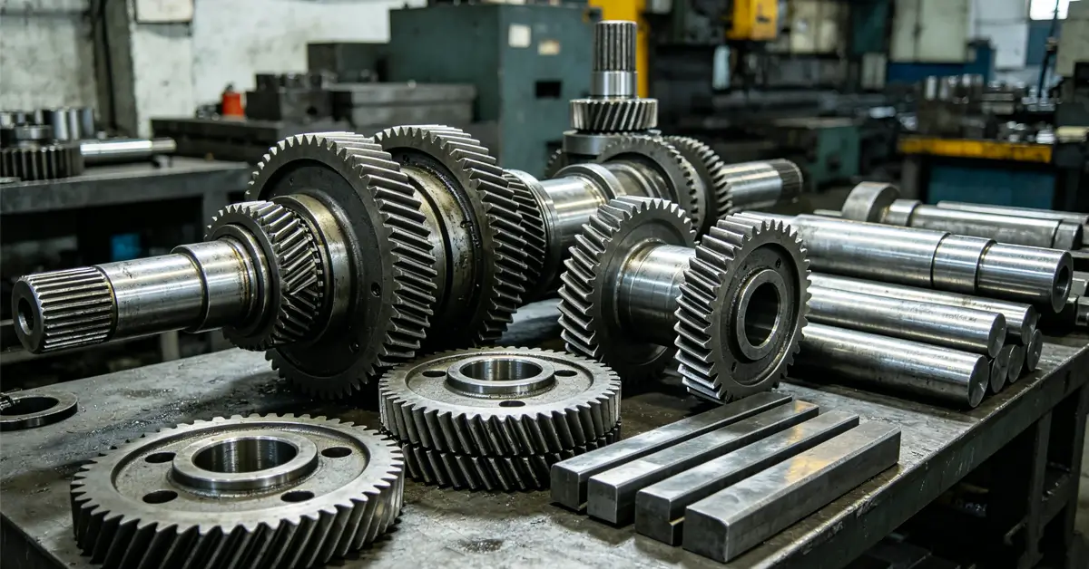
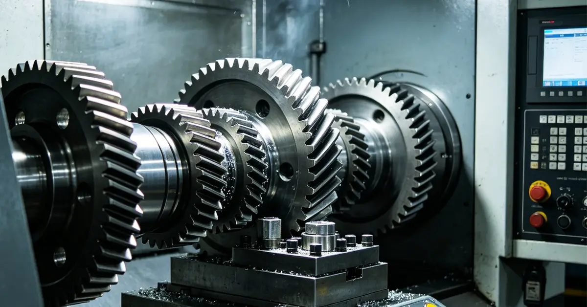
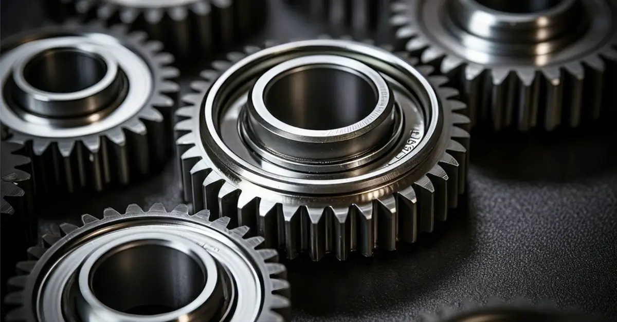
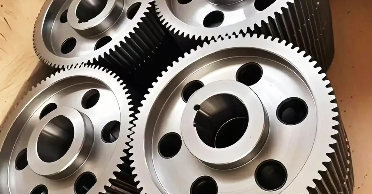
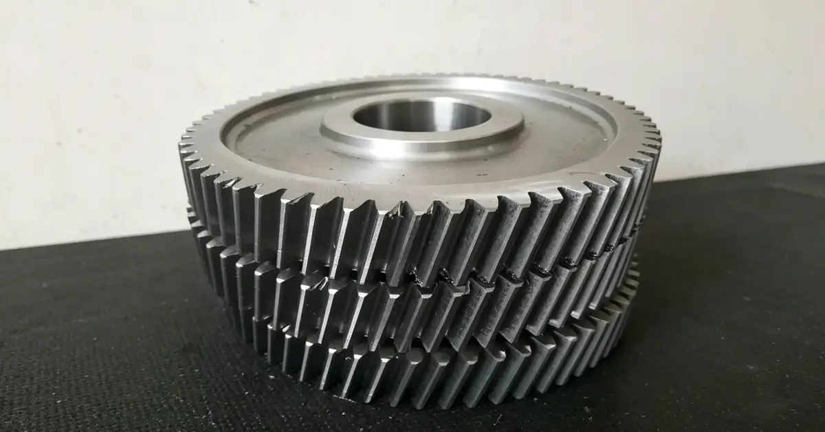
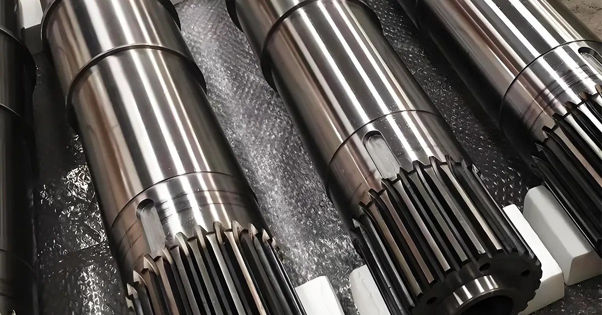
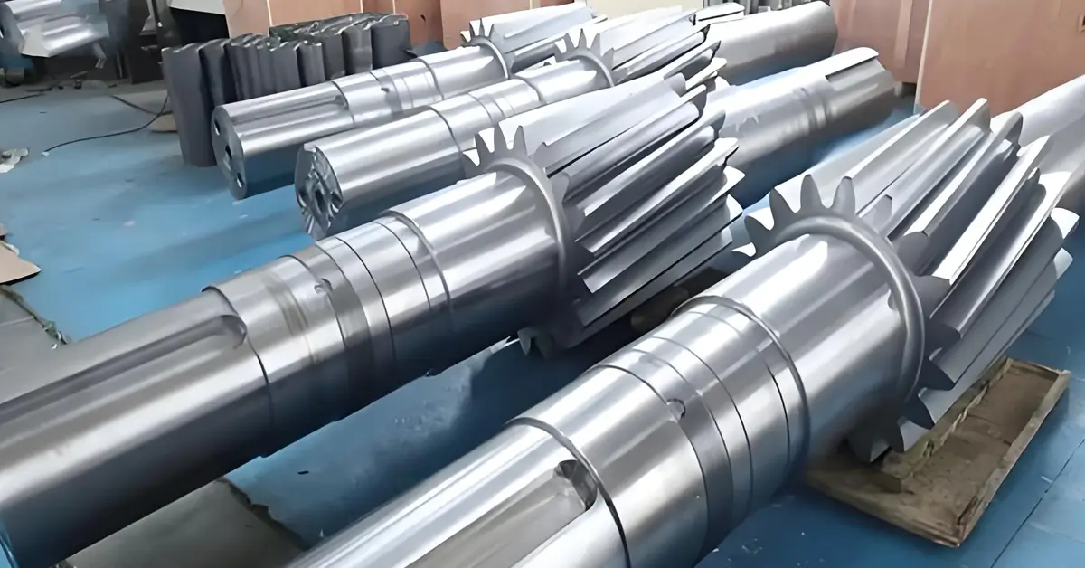
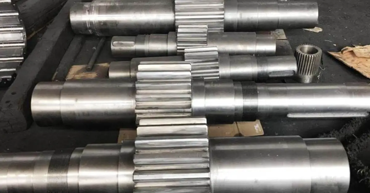
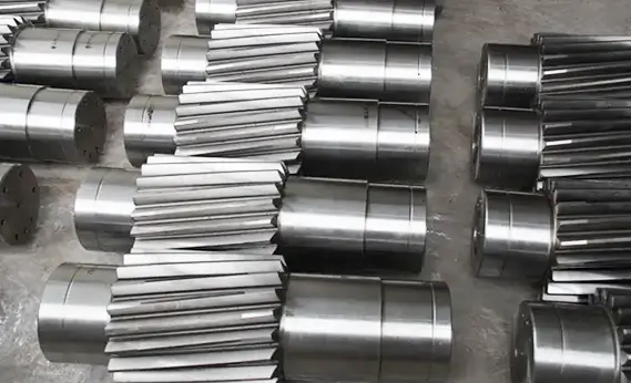
List of Precautions for Gear Machining
1. Core Gear Machining Precautions
As the core component of mechanical transmission systems, gears’ machining quality directly affects equipment operating efficiency and service life. In modern industry, gear machining requires not only high-precision technical support but also strict quality control at every stage to guarantee finished products meet customer requirements. Below are several core gear machining precautions:
1.1 Drawing Review & Confirmation
Prior to machining, a detailed review of gear design drawings must be performed to verify parameters including dimensions, tooth profile, number of teeth, module, pressure angle, accuracy grade and tolerances. Any oversight in design may lead to subsequent machining failure and even impair the performance of the complete machine. Full communication with customers or the design team is recommended. Production can only start after all details are confirmed correct.
Pitfall Avoidance Guide: Strict review is required during the design phase. Experienced gear manufacturers are often able to identify implicit issues not clearly specified on drawings.
1.2 Material Selection & Inspection
The performance and service life of gears largely depend on the quality of selected materials. Common gear materials include alloy steel, carbon steel, stainless steel, etc. Different materials shall be selected for different application scenarios. For instance, high-load industrial gears generally adopt high-strength alloy steel. Nitriding steel is suitable for components requiring high surface hardness, dimensional stability and wear resistance, while stainless steel is preferred for gears operating in corrosive environments. Special attention shall be paid to material hardness, toughness and wear resistance during material selection. At Songjie, we offer customized services ranging from gear raw materials to finish-machined forged gears. We can directly produce steel complying with customer specifications and supply Material Test Certificates (MTC).
Pitfall Avoidance Guide: Chemical composition and internal defects of materials must be rigorously inspected by means of spectral analysis, ultrasonic testing and other methods to confirm compliance with machining requirements.
1.3 Blank Forging and Cutting-off Stage
For this stage, the key gear machining precautions focus on various parameters of the forging process, including:
- Strictly control the forging start temperature and finish forging temperature during forging to ensure the metal flow lines follow the gear contour;
- Prioritize die forging or ring rolling technology to guarantee the metal flow lines at the tooth section distribute along the tooth profile;
- Determine blank dimensions during cutting-off based on forging ratio, burning loss, forging allowance and subsequent machining allowance. Insufficient allowance leaves no room for correction after heat treatment deformation. Excessive allowance increases cutting load, material waste and deformation risk.
Pitfall Avoidance Guide: Normalizing or other pre-treatments are generally required after forging to refine grains, reduce hardness, release partial forging stress and improve machinability. 100% ultrasonic testing shall be implemented on forged blanks to detect internal defects such as cracks, inclusions and shrinkage cavities. Magnetic particle inspection will be carried out on suspicious workpieces to ensure no surface cracks.
As a leading forging manufacturer in the industry, Songjie Forging employs a mature gear forging process that ensures every forged steel gear blank is free from internal shrinkage cavities and cracks, laying a perfect foundation for subsequent machining.
1.4 Rough Turning and Datum Positioning
Unified datum is the core principle. Using the inner bore and end face as positioning datums, rough turning does not machine to final dimensions in one pass. Its purpose is to remove scale and excess metal, and establish stable and reliable datums for inner bore, end face, outer circle or journal. The critical Gear Machining Precautions at this stage are listed below:
- Clamping accuracy: Machine related datum surfaces in a single clamping setup whenever possible and finish all datum surfaces in one clamping to reduce repeated positioning error. If the inner bore and end face are machined in two separate clamping operations, perpendicularity error will be introduced. This error will manifest as runout during gear hobbing, uneven hardened layer in carburizing and inconsistent cutting depth in gear grinding. Soft jaw chucks or expanding sleeve fixtures are recommended to avoid damaging the outer circle. Lock the workpiece after alignment and prevent loosening during machining.
- Clamping force control: Excessive clamping force will directly cause clamping deformation for thin-walled ring gears, while insufficient clamping force tends to induce tool chatter during heavy cutting.
- Allowance control: Machining allowance is a range instead of a safety factor. If the allowance is too small, heat treatment deformation will consume the whole allowance, leaving soft spots or tooth profile errors as the grinding wheel cannot fully clean the tooth surface. If the allowance is too large, the grinding wheel has to remove excessive material beyond its capacity, which will trigger the most hazardous defects of gears.
Pitfall Avoidance Guide: Stress relief annealing shall be arranged after rough machining to release thermal stress and cutting stress and prevent severe distortion in subsequent heat treatment.
1.5 Gear Hobbing / Gear Shaping for Tooth Profile Machining
This is the core operation determining gear profile accuracy and also the most error-prone stage covered in gear machining precautions:
- Gear Hobbing
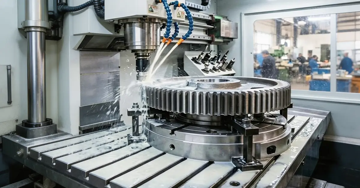
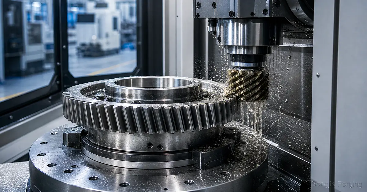
Gear hobbing process is a continuous generating method widely adopted in mass production of external cylindrical gears, applicable to spur gears and helical gears. It features high efficiency and good consistency, yet it imposes high requirements on machine rigidity, cutter condition, workpiece positioning and synchronous motion.
In this stage, verify that hob specifications, pressure angle, helix angle, etc., match the workpiece. Check the runout of tooling, mandrels, centers and fixtures to prevent clamping errors from being introduced into the tooth profile. Set cutting speed, axial feed and cutting depth according to material hardness, module, tooth width and machining allowance. Excessive feed speed will cause chatter marks; insufficient coolant accelerates hob wear and induces thermal deformation.
- Gear Shaping
Gear shaping process is suitable for internal gears, narrow tooth spaces, double gears and certain special structures. Compared with gear hobbing, gear shaping offers better structural adaptability, but efficiency, tool cost and cycle time need to be comprehensively evaluated based on production batch size.
For gear shaping, avoid interference between the cutter and hubs, shaft shoulders or adjacent structures. For internal gears, verify the minimum addendum circle, cutter relief space and post-heat-treatment finishing feasibility during drawing review.
1.6 Heat Treatment Control Stage
Heat treatment is critical for gears to acquire required strength and hardness; meanwhile, it is the operation with the greatest deformation. 90% of cases with insufficient grinding allowance are caused by out-of-control heat treatment. Below are the key gear machining precautions for this stage:
- Deformation prevention: Use tooling fixtures for suspended quenching to avoid deformation induced by self-weight. Load workpieces symmetrically to ensure uniform heating and cooling. Measure deformation after heat treatment; scrap workpieces exceeding reserved allowance in advance to prevent them from flowing into subsequent processes.
- Quenching: Use controlled atmosphere furnaces and martempering to minimize oxidation, decarburization and uneven cooling. Balance the quenching cooling rate: overly rapid cooling leads to large deformation while inadequate cooling results in insufficient hardness.
- Furnace atmosphere: Prevent oxidation and decarburization. A decarburized layer not only reduces surface hardness but may alter residual stress status and raise the risk of grinding cracks in subsequent processing.
- Key loading arrangement: Gears shall be placed flat with uniform support. Do not stack them or suspend eccentrically to avoid warpage and ovality caused by self-weight during quenching.
Pitfall Avoidance Guide: Heat treatment deformation cannot be completely eliminated. Hardened gears of Grade 5 and above must rely on gear grinding for correction; shaving and honing cannot resolve quenching deformation.
1.7 Gear Grinding and Finishing
Gear shaving is generally applied for finishing of soft tooth surfaces prior to heat treatment. Gear grinding is mainly used for high-precision correction after heat treatment. Gear honing focuses more on reducing surface roughness, improving meshing smoothness and lowering noise. For small batches or special tooth profiles, CNC gear milling or form milling can be considered.
During gear grinding, attention shall be paid to wheel dressing, cooling, feed rate and depth of cut per pass. Excessive grinding heat may lead to grinding burn, temper softening, residual tensile stress and microcracks. Gear honing has limited capability to correct geometric errors and cannot replace gear grinding for workpieces with severe deformation. Process selection should not merely depend on “the highest precision”; gear type, batch size, module, material hardness, lead time, equipment capacity and total cost must also be taken into consideration.
Pitfall Avoidance Guide: Whichever high-precision gear machining method is adopted, tooth profile error must be strictly controlled to ensure tooth pitch, tooth height and tooth thickness comply with design requirements. High-precision measuring instruments such as a gear measuring center are recommended to monitor machining accuracy in real time and detect & correct deviations promptly.
1.8 Inspection and Assembly
For finished gears, key inspection items include tooth profile error, tooth lead error, cumulative pitch error, radial runout, tooth surface roughness, hardness and contact pattern. Critical dimensions shall be 100% inspected with complete inspection reports issued. Calipers and micrometers alone are insufficient; precision gears require inspection via a gear measuring center.
Pitfall Avoidance Guide: Assign a unique serial number to each product and record material grade, heat batch number, working procedures and inspector information to achieve full-process traceability.
2. FAQs on Gear Machining Precautions
Q1: What are the most common causes of gear heat treatment deformation?
A: Uneven blank geometry combined with improper control during quenching. Besides, deformation is inevitable in heat treatment; it can only be controlled rather than eliminated. Adopting symmetrical blanks, implementing adequate normalizing treatment and using press quenching (die constrained quenching) can significantly reduce the deformation magnitude.
Q2: What is the most critical point covered in Gear Machining Precautions?
A: No single working procedure can independently determine the final quality. For heavy-load gears, every detail must be well controlled, including material and blank quality, heat treatment, datum consistency and post-heat-treatment tooth surface finishing.
Q3: How to prevent deviations between actual outer diameter, inner bore or tooth pitch and design dimensions in gear machining?
A: Calibrate machining equipment regularly to guarantee its precision. Apply high-precision measuring tools for real-time inspection during machining and adjust process parameters promptly.
3. Conclusion
Beyond the above points, gear machining precautions also cover equipment and tool calibration, cutter selection and more. Oversights in any single process stage may result in excessive noise, wear, or even catastrophic gear failure. At Songjie, we maintain a complete professional gear machining process. From drawing review to finished product inspection, we follow specifications strictly at every step, committed to manufacturing high-precision, high-quality, long-service-life gears that meet your requirements.
If you are searching for a forged gear and forging manufacturer with one-stop capabilities covering forged blank, precision machining and heat treatment, feel free to send us your drawings for inquiry to receive drawing evaluation and a prompt quotation.
Related Articles
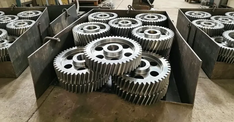
Steel Gear Applications Guide for Different Materials
Gain insights into diverse steel gear applications covering automotive, aerospace, construction machinery, food processing and medical industries, helping you select optimal materials accurately to cut costs and boost efficiency.
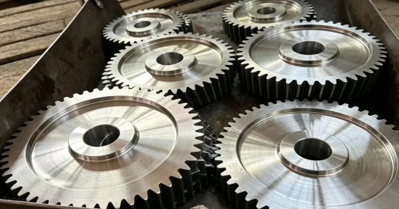
Uncovering Performance Advantages of Steel Gears Made from Diverse Materials
In-depth analysis of performance advantages of mainstream steel gear materials including alloy steel, stainless steel, tool steel and carbon steel to fully meet your application requirements-Songjie provides custom high-quality steel gears manufactured from a full range of materials.
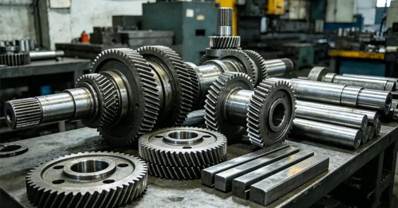
What Level of Transmission Noise Is Determined by Mechanical Gear Materials?
Different selections of mechanical gear materials bring different transmission noise levels, Songjie can customize mechanical gears with various raw materials, we compare diverse gear materials to fit your actual demands.