
Forged Gear: Key Considerations in the Forging Process
Gears are critical components widely used in mining conveyors, wind turbine gearboxes, automotive transmission systems, and various types of mechanical equipment. When a gear fails, the failure can often occur suddenly and may result in serious operational and safety consequences. Therefore, every stage of the forged gear manufacturing process requires strict quality control, with careful attention to every detail. This guide provides a stage-by-stage overview of the key considerations in forged gear manufacturing, with a focus on process control, quality assurance, and the production of high-quality gear forgings.
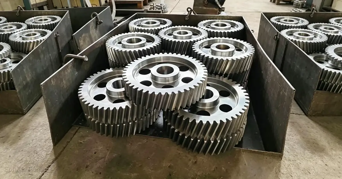
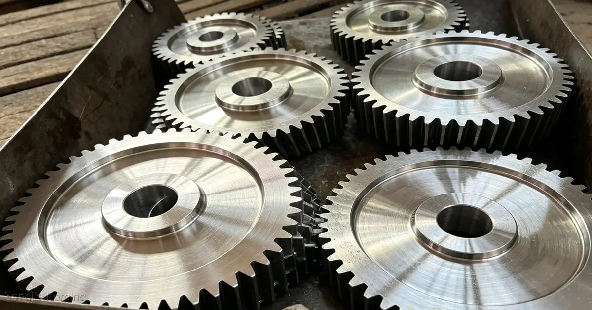
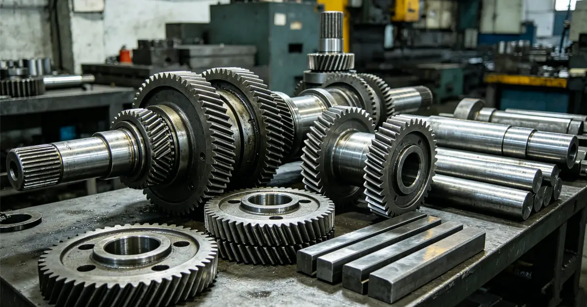
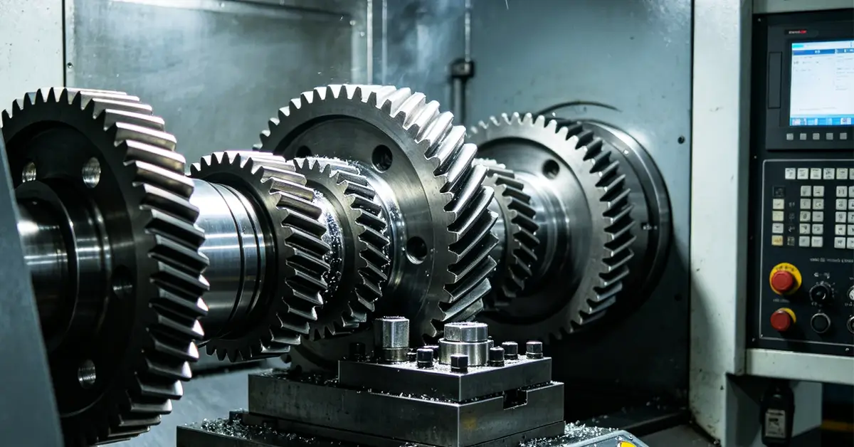
The Importance of Process Control in Forged Gear
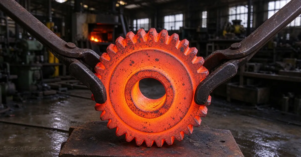
Why is process control more important than ever in forged gear manufacturing? From wind turbines and mining mills to marine propulsion systems and rail transportation, the growing global demand for heavy-duty power transmission components has made steel gears a key focus of the supply chain. Unlike cast gears or gears produced solely through machining, forged gears feature continuous metal flow lines (grain flow) that follow the gear’s geometry, providing superior fatigue resistance under impact and cyclic loading.
However, these advantages can only be fully realized when every stage of the manufacturing process is strictly controlled. At Songjie Forging, we implement end-to-end process control throughout the entire manufacturing process to ensure consistent quality, structural integrity, and reliable performance of our forged gears.
Key Considerations in the Gear Forging Process
Stage 1: Confirm the Drawing and Operating Conditions
Before forging begins, the gear’s actual operating conditions must be clearly defined rather than quoting based solely on the outside diameter and number of teeth. At a minimum, the following parameters should be confirmed: module or diametral pitch, number of teeth, pressure angle, helix angle, face width, outside diameter and root diameter, center bore or shaft configuration, direction of rotation, input power, rotational speed, degree of impact loading, operating temperature, lubrication conditions, and required service life.
Special Note: Before providing a quotation, the supplier should request the 2D engineering drawing, 3D model, material specification or standard, heat treatment requirements, non-destructive testing (NDT) level, gear accuracy grade, and inspection standards. Without this information, a low-cost quotation may represent only the forged blank price rather than the price of a finished gear ready for installation.
Stage 2: Material Selection and Verification
Poor-quality steel cannot produce high-quality forged gear. This is one of the most common—and most costly—mistakes in gear forging. The following factors should be carefully considered at this stage:
- Material Cleanliness: Specify low sulfur and low phosphorus levels whenever the application requires high cleanliness. Excessive sulfur can reduce toughness and ductility and may contribute to cracking and poor impact performance, particularly in demanding applications such as wind power and low-temperature or polar environments.
- Material Inspection: Require ultrasonic testing (UT) of steel billets and ingots to identify internal discontinuities. Internal defects such as porosity and shrinkage cavities in the original material cannot necessarily be eliminated simply through forging; depending on their size, location, and forging reduction, they may be redistributed, elongated, or closed rather than completely removed. Chemical composition analysis, surface inspection, hardness testing, and other material verification procedures should also be carried out as required.
- Material Selection: Select the steel grade according to the gear’s operating conditions and performance requirements. For gears operating under high-stress conditions, such as automotive transmissions, wind turbine gearboxes, and marine propulsion systems, alloy steels such as 20CrMnTi, 42CrMo4, and 18CrNiMo7-6 are commonly used. For specialized applications requiring very high wear resistance, tool steels such as H13, SKD61, D2, and Cr12MoV may be considered. The appropriate material ultimately depends on factors such as gear load, rotational speed, operating environment, required wear resistance, fatigue performance, and heat treatment requirements.
Stage 3: Forging Blank Preparation
Forging blank preparation has a direct impact on die life and material utilization. A standard process typically includes blank cutting, heating, and initial upsetting.
- Blank Cutting: Ensure that sufficient machining allowance is reserved on all relevant surfaces to remove the decarburized layer after forging and heat treatment. Potential distortion or bending during heat treatment should also be taken into consideration. Blank weight must be controlled within strict tolerances to prevent insufficient filling or excessive die loading.
- Heating: For gear steels, excessive heating temperatures can cause grain growth, reduced toughness, and excessive decarburization, while insufficient heating increases deformation resistance and die wear. The heating rate must also be carefully controlled, particularly for large-diameter blanks, to minimize the risk of thermal cracking.
- Upsetting: The initial forging operation, or upsetting, serves two purposes: forming the blank into a disc-like shape and helping break and remove surface scale. If this operation is performed too quickly and the oxide scale is not adequately fractured and removed, oxide particles may become entrapped in the material during subsequent forging operations and potentially create surface defects on the gear.
- Chamfering: Deburr and chamfer cut edges before forging to reduce the risk of cold shuts and laps during the forging process.
- Material Cutoff / Charge Weight: The blank weight must be accurately calculated. Too little material may result in incomplete filling of the tooth tips, rim, or die cavity, while excessive material can increase flash formation, folding defects, die loading, and the amount of material requiring subsequent trimming.
Stage 4: Forged Gear
This is the core stage of the gear forging process and one of the most critical stages for controlling product quality.
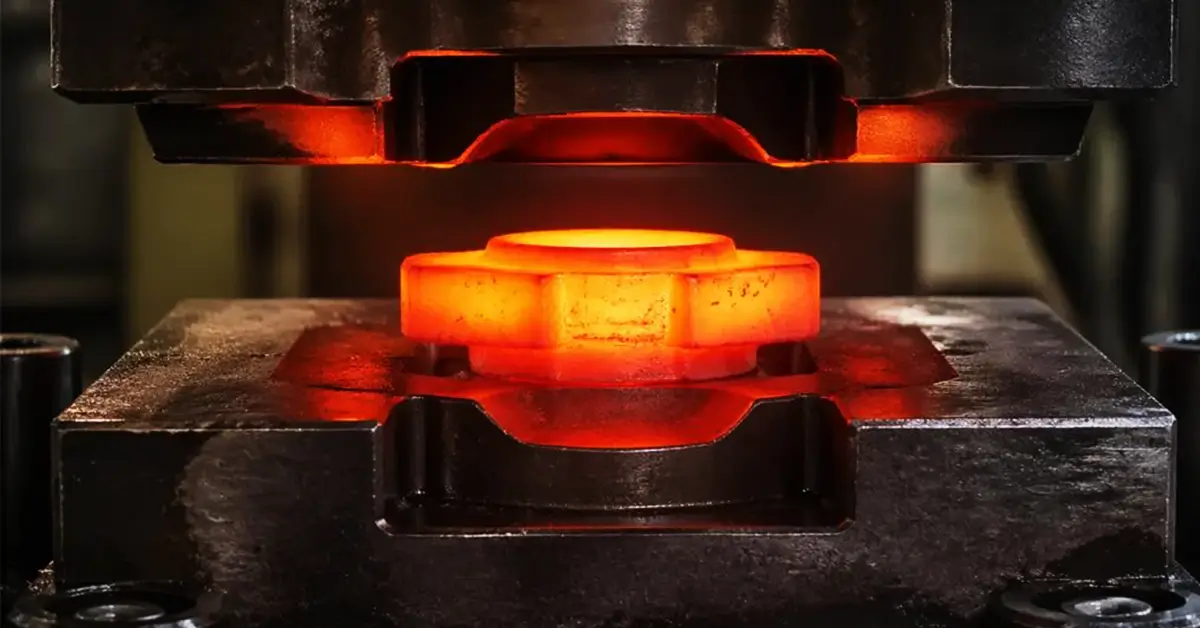
- Select the Appropriate Gear Forging Method: Use closed-die forging (impression-die forging) for high-precision, near-net-shape components and medium- to high-volume production. Open-die forging is generally used for large or complex-shaped components, particularly for low-volume or one-off production. When the gear teeth require near-net-shape or net-shape accuracy, precision forging should be considered.
- Metal Flow and Grain Flow Distribution: The die design must guide the metal flow so that the grain flow follows the gear geometry, particularly around the tooth root, where stress concentration is typically highest. This is one of the major metallurgical advantages of forged gear over cast gear. If the grain flow is severely interrupted or folding occurs around the tooth root, fatigue performance can be significantly reduced.
- Control the Forging Reduction Ratio: Insufficient deformation can result in coarse grains, reduced mechanical strength, and shortened fatigue life. A minimum required forging reduction ratio should therefore be established based on the material, starting stock, and forging process, and its achievement should be verified.
- Flash Formation: Controlled flash formation is generally permitted in closed-die forging to ensure that the die cavity is completely filled. Excessive flash may indicate excessive material or an improper charge weight, while insufficient flash may indicate insufficient blank weight, inadequate material flow, or an excessively low forging temperature.
- Ensure Uniform Loading and Avoid Localized Deformation: During forging, the blank should be subjected to relatively uniform deformation. For gears with complex geometries, multiple forging heats and progressive forming should be used rather than attempting to achieve the final geometry in a single operation. Excessive deformation in one step can increase the risk of laps, cracks, and eccentricity. This is particularly important for gears with hubs, where the deformation behavior of the hub/core region differs from that of the rim. The deformation should therefore be introduced progressively, with the amount of deformation at each stage carefully controlled.
FAQ: Key Considerations for Forged Gear
Forged gears have a dense, refined forging structure, with continuous metal flow (grain flow) following the gear geometry. This can improve tensile strength, toughness, and fatigue resistance when the forging process is properly controlled.
Cast gears, in contrast, may contain internal defects such as porosity, inclusions, or shrinkage cavities, while their solidification structure does not provide the same directional grain flow as a forged component. Cast gears can be suitable for certain large components and applications with moderate stress, depending on the casting quality and design requirements. For heavy-duty power transmission applications, forged gear blanks are commonly selected when high strength and fatigue resistance are required.
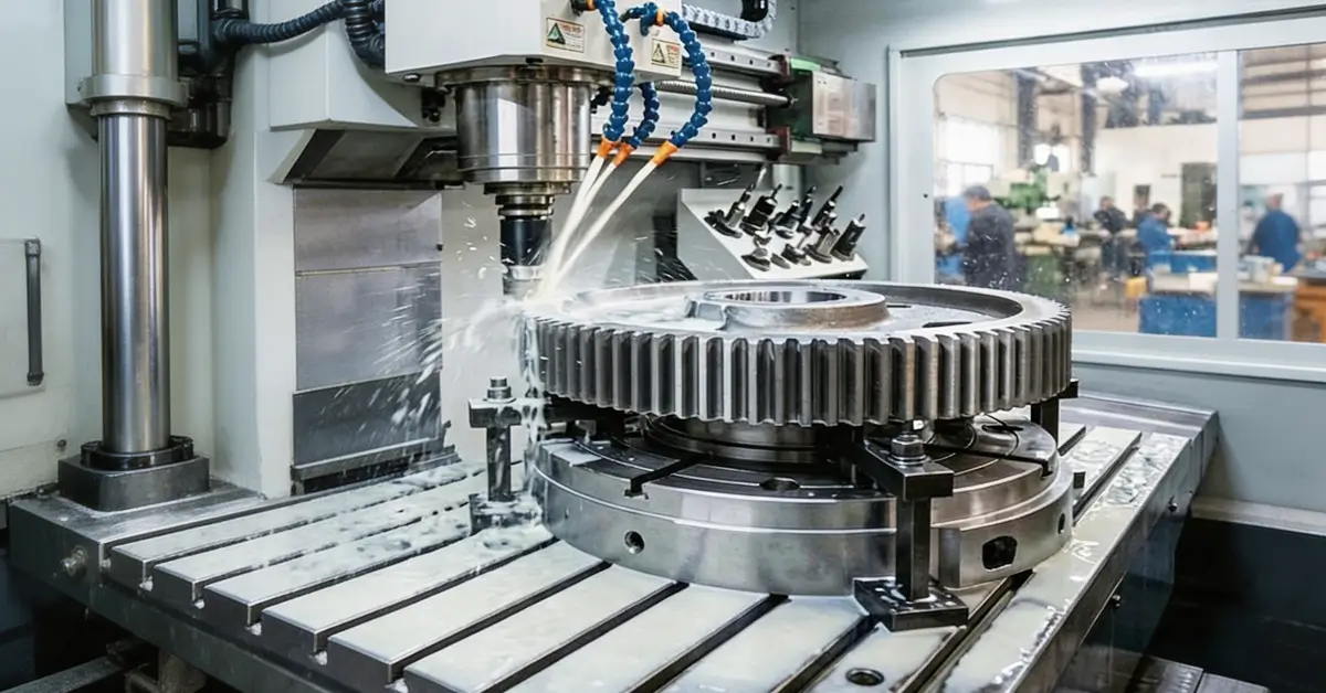
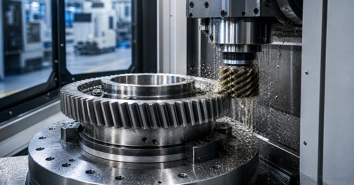
Some spur gears, helical gears, and ring gears can be produced close to their final geometry through precision forging. However, most applications still leave machining allowance for processes such as hobbing, gear shaping, gear grinding, or localized finish machining.
The higher the required gear accuracy grade, the more important it is to define the final machining route and dimensional requirements during the quotation stage.
When evaluating a gear forging manufacturer, consider the following capabilities:
- Steel supply: Does the manufacturer have an in-house or stable steel supply system?
- Material traceability: Can the manufacturer provide complete material traceability and relevant material certificates?
- Forging capacity: Does the manufacturer have suitable large-scale forging equipment and closed-die forging capabilities?
- Process validation: Can the manufacturer perform forging simulation, die-flow analysis, and process validation?
- Heat treatment and machining: Does the manufacturer have in-house or controlled capabilities for heat treatment, machining, and gear inspection?
- Customization: Can the manufacturer provide customized forging solutions according to drawings, materials, dimensions, and performance requirements?
- Delivery capability: Can the manufacturer consistently meet dimensional tolerances, weight requirements, production quantities, and agreed delivery schedules?
Conclusion
In addition to the considerations discussed above, forged gear also requires careful control of post-forging cooling and heat treatment, machining, inspection, and quality control. Ensuring gear quality is not dependent on a single critical step; instead, it relies on strict control and effective coordination throughout every stage of the manufacturing process.
At Songjie Forging, we also provide preventive solutions for common gear forging defects, helping customers identify potential process risks and improve forging quality. With a focus on process control and consistent manufacturing standards, we are committed to producing high-quality gears that meet demanding application requirements.
Explore our full range of forged shafts, forged discs, forged cylinders, and forged gears, backed by more than 20 years of forging expertise.
Related Articles
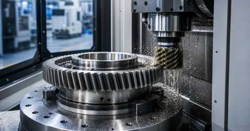
Complete Gear Machining Process
What steps does gear machining involve? This article walks you through the complete gear machining process of Songjie, covering drawing review, material selection, forging, turning, gear tooth machining, heat treatment, finished‑product inspection, and more.
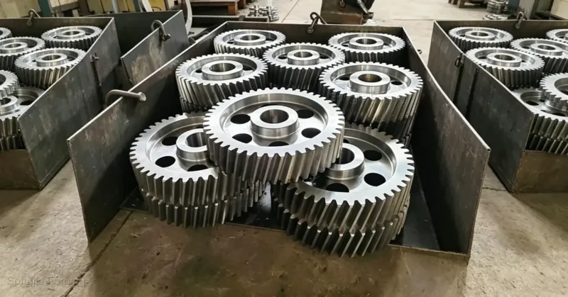
Steel Gear Applications Guide for Different Materials
Gain insights into diverse steel gear applications covering automotive, aerospace, construction machinery, food processing and medical industries, helping you select optimal materials accurately to cut costs and boost efficiency.
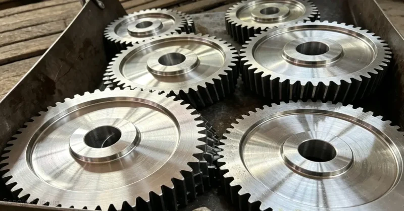
Uncovering Performance Advantages of Steel Gears Made from Diverse Materials
In-depth analysis of performance advantages of mainstream steel gear materials including alloy steel, stainless steel, tool steel and carbon steel to fully meet your application requirements-Songjie provides custom high-quality steel gears manufactured from a full range of materials.