Structural Design Principles of Stepped Shaft Forgings
In mechanical transmission, marine propulsion systems, heavy equipment, precision instruments and many other fields, stepped shaft forgings are the core components for transmitting motion and torque in mechanical engineering. The rationality of their shape and structure directly determines the stability, service life and processing cost of the entire machine. A seemingly simple stepped shaft hides numerous complex processes and details behind it. This paper disassembles a standard system to analyze every key dimension of the structural design of stepped shafts supplied by Songjie, aiming to provide you with high-quality shaft forgings and help you better understand and apply these design principles.
I. What is a stepped shaft forging, and why is structural design so critical?
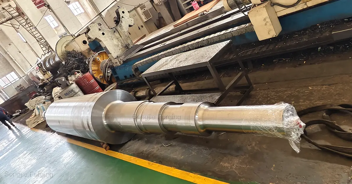
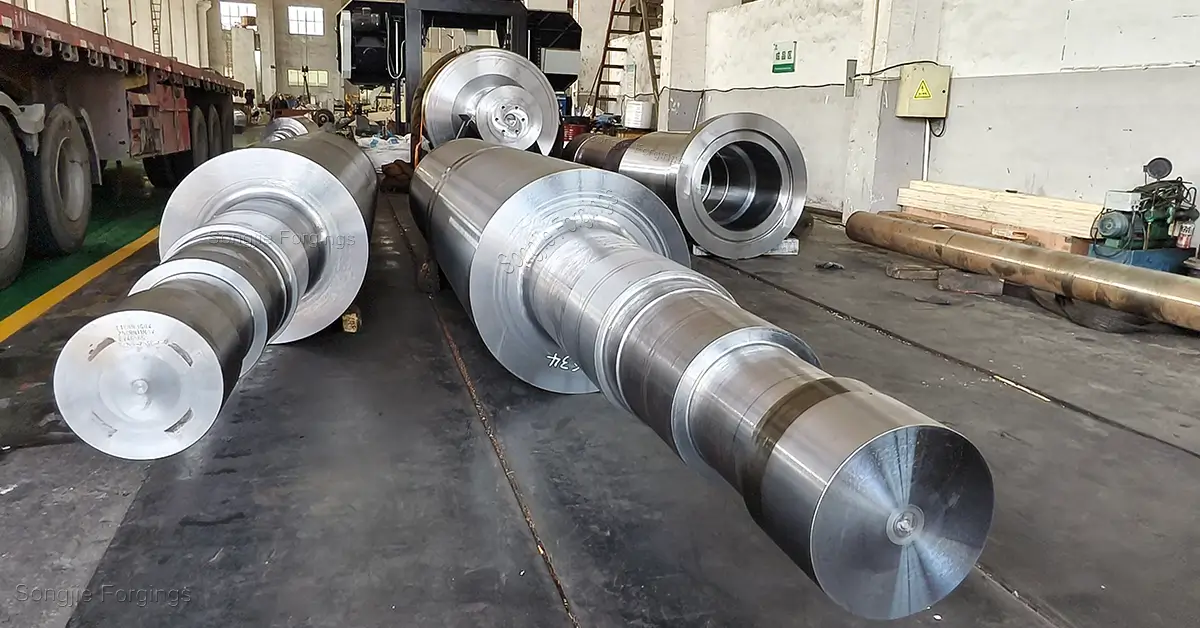
Stepped shaft forgings are core components for torque transmission and supporting rotating parts. They are characterized by multiple cylindrical sections of varying diameters along the axis, resulting in a more complex structure. Stress concentration at shaft shoulder transitions, precise positioning of keyways, and rational design of relief grooves—every single detail can act as a trigger for fatigue failure.
Engineering Warning: Statistics show that more than 60% of early failures in transmission shafts stem from neglect of stress concentration or unreasonable structural design during the design phase. Minor consequences include difficult assembly, oil leakage, and misalignment; severe outcomes involve fatigue fracture and equipment downtime, which directly erode your delivery schedule and profits.
At Songjie, we strictly standardize the geometry, tolerance requirements, and quality acceptance of stepped shaft forgings. We achieve optimal structural design within the framework of standards to provide customers with the best stepped shaft products.
II. Complete Process of Stepped Shaft Design
A standardized stepped shaft forgings design process must comprehensively consider strength, stiffness, structural manufacturability and other factors. It generally includes the following core steps:
1. Soul-Searching Before Design: What Does the Shaft “Require”?
1.1 Define Service Conditions and Design Inputs
Before design, the following service conditions must be clearly defined:
◆Application scenario and function of the shaft.
◆Transmitted power \( P \) (kW) (or torque) and rotational speed \( n \) (r/min).
◆Load type: static load, constant load, variable load, impact load, etc., as well as load magnitude and direction.
◆Working environment: temperature, corrosive media, lubrication conditions, cleanliness requirements.
◆Service life requirement and reliability level.
Design Tip: Service conditions directly determine the selection of safety factors and material grades. It is recommended to establish a complete Design Input List at the initial stage of the project, to provide a basis for subsequent material selection, structural design and strength verification.
1.2 Selection of Shaft Materials and Surface Treatment Methods
Material selection for stepped shaft forgings shall balance strength, toughness, machinability and cost efficiency. Choosing the right material plus refined surface treatment is often more economical than simply increasing shaft diameter. Common material systems are as follows:
◆ General load: Grade 45 carbon steel (quenched and tempered), with excellent comprehensive performance, serving as the most economical mainstream material.
◆Heavy load / High speed: 40Cr, 42CrMo, 42CrMoA, 34CrNiMo6 alloy structural steels. After quenching and tempering plus induction hardening, they provide higher fatigue strength.
◆High precision / Corrosion resistance: Stainless steel shafts (e.g. 2Cr13, 4Cr13, 1Cr18Ni9Ti), solution treated, suitable for food, chemical and other special applications.
◆Ultra-heavy load: 18CrNiMo7‑6 carburizing steel, balancing core toughness and surface hardness.
For surface treatment, Songjie can select according to working conditions: high-frequency quenching (local strengthening), carburizing and quenching (overall strengthening), anodizing / hard anodizing (improving hardness, wear resistance and corrosion resistance), nitriding (enhancing wear resistance and fatigue resistance), shot peening (improving fatigue strength), chrome plating (corrosion and wear resistance), etc.
Note: All surface strengthening processes must be completed before final machining; otherwise, dimensional control will be lost.
1.3 Preliminary Estimation of Minimum Shaft Diameter
The preliminary estimation of the minimum shaft diameter involves using strength formulas to estimate the minimum shaft diameter based on the transmitted torque or bending moment, bending strength, etc., serving as a reference for subsequent structural design. The specific approach is to convert the transmitted power and rotational speed into torque; estimate the minimum shaft diameter based on torsional strength or allowable stress; if there is a superposition of bending moment and torque, the diameter under the combined stress must be considered; and then appropriately increase the diameter based on safety factors and fatigue requirements.
III. Core Principles of Stepped Shaft Structural Design
Principle 1: Positioning and Fixing
Parts mounted on the shaft, such as gears, bearings, and couplings, must be reliably fixed through reasonable axial and circumferential positioning. This is the foundation for stable operation of a stepped shaft. Positioning is critical to maintaining stability during operation of stepped shaft forgings, while fixing ensures no displacement or loosening occurs in service. Common positioning methods are as follows:
Axial Positioning Methods
◆Shaft ring / shaft shoulder + shaft end retaining ring: The most common axial positioning method, with simple structure and high load capacity.
◆Sleeve + round nut + lock washer: Sleeves are used for small spacing between adjacent parts; round nut + lock washer combinations are applied for large spans. Suitable for preloading applications (e.g., angular contact bearing sets), enabling precise adjustment of axial clearance, improving both stability and durability.
◆Circlip (E-type / C-type retaining ring): Used for light loads or auxiliary positioning. Easy to install but with limited load capacity; not recommended as the primary axial fixing method.
Design Tip: The fillet radius R at shaft shoulder transitions must be larger than the chamfer or fillet radius of mating parts; otherwise, effective positioning cannot be achieved.
Circumferential Positioning Methods
◆Key connection: Parallel keys, semicircular keys, splines — suitable for most torque transmission applications.
◆Interference fit: For high-precision transmission, keyless, high torque capacity, but difficult to disassemble.
◆Pin connection: Used for precise angular positioning or anti-rotation.
Design Principle: On the same shaft section, axial positioning surfaces and circumferential positioning should be independent and non-interfering, to avoid statically indeterminate constraints that cause assembly stress.
Principle 2: Ease of Assembly and Disassembly
An excellent stepped steel shaft design must consider manufacturability for assembly from the very beginning. The design shall follow the logic of assembling from the larger diameter to the smaller diameter step by step, so as to prevent reverse steps that make part installation impossible. Meanwhile, reasonable shaft end chamfers, guiding tapers, and removal of sharp edges and burrs shall be applied to reduce assembly difficulty and improve efficiency:
◆Diameters of each shaft section shall increase step by step from both ends toward the center (or comply with the step-increment principle), ensuring smooth mounting of components.
◆Lead-in chamfers shall be designed at shaft ends for easy alignment during assembly, avoiding scratching mating surfaces or jamming.
◆For bearing positions requiring disassembly, the shaft shoulder height shall not exceed the width of the bearing inner ring, leaving space for disassembly tools.
◆Designers shall ensure fast and accurate assembly of all shaft sections to improve productivity and reduce costs.
◆The number of steps shall be strictly controlled. The number of diameter changes shall be minimized while satisfying positioning requirements. Unified chamfer and fillet dimensions simplify machining, greatly improve assembly efficiency, and reduce labor and time costs.
◆Excessively high steps or overly sharp shoulders shall be avoided, as they may cause difficult assembly or tool interference.
Common Mistake: Many designers neglect to set disassembly process grooves on shaft journals for shrink-fitted parts, resulting in destructive disassembly during maintenance and a significant increase in life-cycle cost.
Principle 3: Minimization of Stress Concentration
In stepped shaft forgings, stress concentration occurs at geometric discontinuities such as shaft shoulders, keyway roots, and thread roots, which is the root cause of fatigue crack initiation. Design measures to extend service life and reduce stress concentration include:
◆Shaft shoulder fillet transition: Use large fillet transitions preferentially and avoid right-angle transitions. The fillet radius must be smaller than the chamfer of the bearing inner ring. If necessary, undercut fillets can be used to increase the transition radius.
◆Keyway ends: Use ball-end keyways instead of square-end keyways to reduce the stress concentration factor.
◆Step ratio: The diameter ratio \(D/d\) of adjacent shaft sections should be controlled between 1.05 and 1.30 to avoid excessive steps.
◆Surface strengthening: Apply strengthening treatments such as induction hardening, carburizing, and shot peening to stress-concentrated areas to introduce compressive stress, which can improve fatigue life by more than 30%.
◆Avoid transverse holes and sharp corners: Strive to avoid any transverse holes, sharp corners, and sharp edges in the design.
◆Advanced profile curves: For shafts requiring high fatigue life, traditional fillets can be replaced by streamlined transition curves, which reduce the stress concentration factor more effectively.
Golden Design Rule: Under the same dimensional constraints, increasing the transition fillet radius from \(r = 0.5\ \text{mm}\) to \(r = 2\ \text{mm}\) can improve fatigue strength by approximately 20%. This is the most cost-effective design optimization method.
IV. Key and Keyway Design
Key connection is the core structure for torque transmission in stepped shaft forgings. The design of keyways directly affects transmission reliability and the fatigue strength of the shaft.
Selection and Dimension Determination
Common types include parallel keys, semicircular keys, and taper keys. During design, the key specification shall be selected according to the transmitted torque and shaft section diameter, in strict compliance with supporting standards such as GB/T 1096, to ensure the fitting accuracy of keys and keyways.
The cross-sectional dimensions of the key must be selected in accordance with national standards: an excessively deep keyway weakens shaft strength, while an excessively shallow one easily leads to crushing failure.
Keyway Design Considerations
In stepped shaft forgings, stress concentration occurs at geometric discontinuities such as shaft shoulders, keyway roots, and thread roots, which is the root cause of fatigue crack initiation. Design measures to extend service life and reduce stress concentration include:
◆Keyways should be arranged in low-stress regions of the shaft, avoiding high-stress zones near shaft shoulder fillets.
◆Multiple keyways on the same shaft should be aligned on the same axial line (same phase) to improve positional accuracy and facilitate milling.
◆The tolerance of keyway depth has a significant influence on fit characteristics and must be strictly implemented in accordance with GB/T 1095.
◆Fillet radius at keyway root: r ≥ 0.25 × keyway width; sharp corners are not permitted.
◆For small shaft diameters (d < 22 mm), semicircular keys are preferred due to better self-centering performance.
◆Keyways should not be placed in weak sections of components, and the fillet radius at the groove bottom must be sufficiently large to reduce stress concentration.
Applications of Spline Connections
When a single-key connection cannot meet torque transmission requirements, or when axial movement is required (such as in sliding gears or clutches), a spline connection should be selected. Rectangular splines (GB/T 1144) offer high centering accuracy, while involute splines (GB/T 3478) have strong load-bearing capacity and are commonly used for heavy-duty or high-precision connections (such as aero-engine shafts). The appropriate spline should be selected based on the actual operating conditions.
V. Key Process Structures: Undercut Grooves, Grinding Wheel Relief Grooves and Center Holes
Although these three process structures may seem insignificant, they are critical details that determine whether a stepped shaft can be machined smoothly and assembled reliably. A production-ready stepped shaft drawing cannot be completed without these “small details”: undercut grooves, relief grooves and center holes.
Undercut Grooves (Turning Undercuts)
When turning threads, splines or finishing surfaces, the cutting tool requires an exit space. Undercut grooves are provided to ensure smooth tool retraction and avoid stress concentration, preventing interference between the tool and the component.
Grinding wheel relief grooves are used in grinding operations to prevent the wheel from damaging the shaft surface.
◆Groove width and depth must satisfy machining requirements without becoming new sources of stress concentration.
◆Reserve undercut grooves when turning threads or shoulders to avoid tool marks on working surfaces. Undercut width should be greater than tool width to prevent interference.
◆Dimensions and geometry of undercuts shall meet process requirements, with rounded transitions preferred.
Machining Tip: Missing undercut grooves are among the most common causes of workshop rework. After threading, if the tool has no space to retract, the drawing must be revised, resulting in both schedule delays and cost increases.
Grinding Wheel Relief Grooves
For shaft sections requiring cylindrical or face grinding, grinding wheel relief grooves must be designed at the junction with adjacent sections. They ensure the grinding wheel can completely traverse the machined surface, achieve uniform precision, and reduce stress concentration.
◆For high-precision bearing seats, sufficient operational clearance shall be structurally reserved for grinding.
◆Grooves shall be located away from high-stress sections, which can be balanced by adjusting shoulder positions and groove widths.
◆Relief grooves shall be tangent to ground surfaces to avoid steps that impair fitting accuracy.
Center Hole Design
Center holes serve as the datum for stepped shaft manufacturing throughout turning, grinding and inspection, providing positioning and support. Therefore, proper center hole design is essential:
◆Type A center holes (without protective cone): For parts where center holes are not retained.
◆Type B center holes (with protective cone): Standard recommended type; retained center holes facilitate later repair and machining, with a 60° cone angle.
◆Center hole dimensions are selected per GB/T 145 according to shaft mass and length.
◆Center holes at both ends must have excellent coaxiality — this is fundamental to ensuring machining accuracy.
◆The type, depth and position of center holes shall comply with standards to avoid weakening shaft end strength.
Engineering Experience: For critical transmission shafts, retaining Type B center holes is strongly recommended. They provide a reliable datum for subsequent repair grinding and significantly reduce maintenance costs. Furthermore, center holes must be machined before heat treatment after forging!
VI. Load Calculation and Shaft Verification: Final Validation of the Design
Load Calculation on the Shaft
Establish the force model of the shaft and accurately calculate all loads acting on it, including bending moment, torque and axial force, then draw bending moment diagrams and torque diagrams. Analyze the bending moment \(M\), torque \(T\) and axial force \(F_a\) acting on each section:
◆Draw bending moment diagrams and torque diagrams of the shaft to identify critical sections.
◆Calculate the resultant bending moment: M{\text{resultant}} = √(MH² + MV²)
◆Consider load dynamic coefficients (shock coefficients) to correct the applied loads.
Shaft Verification Calculation
◆ Strength Verification: Perform torsional strength, bending strength, static strength and fatigue strength verification on the critical sections of stepped shaft forgings to ensure no plastic deformation or fatigue fracture occurs under maximum load.
◆Stiffness Verification: Verify bending deformation and torsional deformation of the shaft to ensure they are within allowable limits, avoiding adverse effects on transmission accuracy and system stability.
◆Critical Speed Verification: For high-speed rotating shafts, critical speed must be checked to avoid resonance caused by proximity to the operating speed.
VII. Design Improvement
If the shaft fails to pass load calculation and verification, the design must be revised and re‑analyzed. If verification is passed, the basic structure of the stepped shaft forging is confirmed, and we further improve the design from the following dimensions:
◆Tolerances and fits: Clearly specify dimensional tolerances (h6/k6/m6, etc.) and geometric tolerances (cylindricity, coaxiality) for bearing positions and mating sections.
◆Surface treatment: Anodizing improves corrosion resistance for outdoor equipment; Coating enhances wear resistance for high‑frequency friction applications.
◆Heat treatment specification: Define quenched and tempered hardness range (e.g. HB 220–260), local hardening areas and corresponding hardness requirements.
◆Material specification:Specify material grades in accordance with standards such as GB/T 11352, and state mechanical property acceptance requirements.
◆Detail optimization: Chamfers, fillets and technical notes must be fully defined.
◆ Design DFMEA: Conduct potential failure mode and effects analysis for key structures to identify design risks in advance.
◆Process integration: Optimize structural details by combining forging, machining and assembly processes; improve drawing annotations and technical requirements to form a GB‑compliant, mass‑producible solution that balances quality and production efficiency.
Many other details require careful refinement. Only then is a stepped shaft forging design that meets GB, balances manufacturability and operational reliability truly completed.
Summary
In summary, the design of stepped shaft forgings is a complex and systematic engineering task. It covers the entire process from requirement definition → material selection → calculation → process design → verification → optimization. Every design decision shall be based on engineering data and standard specifications. At Songjie, we are committed to providing various types of stepped shafts, and delivering forgings with high reliability, low cost, excellent toughness and durability.